
Rover
Supplies
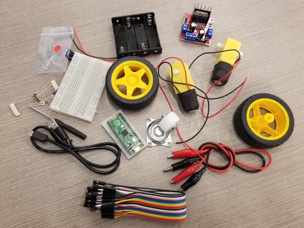
- Raspberry Pi Pico with pre-soldered Header Pins (this is important!)
- USB to Micro USB Cable, 1.5 ft
- 2x DC Gear Motors with Plastic Tire Wheels
- Miniature Castor Wheel
- Motor Driver Board (L298N)
- Battery Holder for 4 – AA Batteries
- Half-size 400-Pin Breadboard
- 2 – White LEDs
- 2 – Red LEDs
- 4 – 100 Ohm Resistors
- 20 – Female-Male Jumper Wires
- 20 – Male-Male Jumper Wires
- Miniature Push Button
- Small Phillips Screwdriver
- Cardboard box for rover chassis
- Scissors
- Masking tape
- 4 – AA Batteries
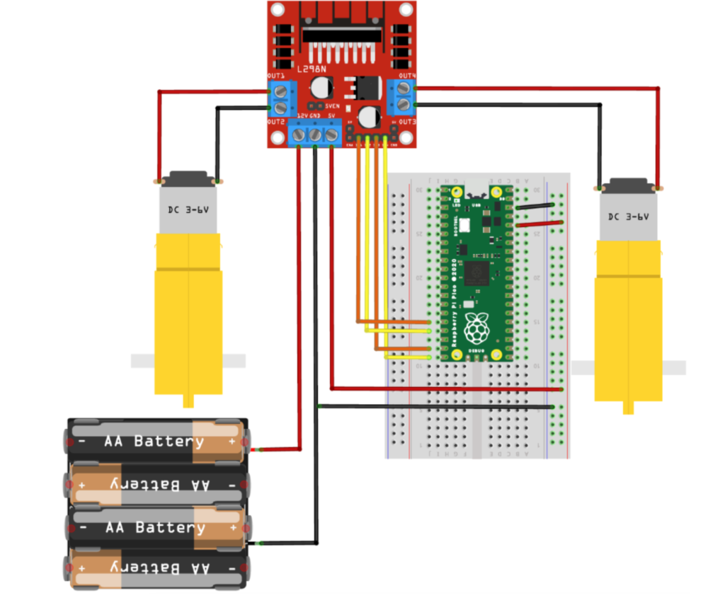
Step 1 – Motor Controller
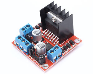
Motor Controller
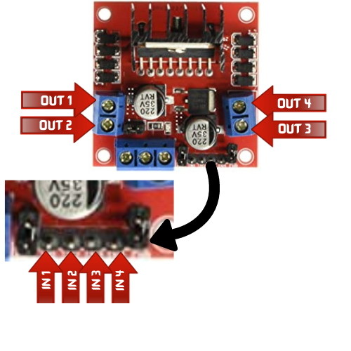
- Loosen the terminals with a screwdriver and connect OUT 1 and OUT 2 to one motor and tighten the terminal screws.
- Connect OUT 3 and OUT 4 to the other motor and tighten the terminal screws.
- IN 1 and IN 2 will be the input controls for one motor, while IN 3 and IN 4 will be the input controls for the second motor.
- Attach the female end of 2 male-to-female jumper cables, one to IN1 and the other to IN2.
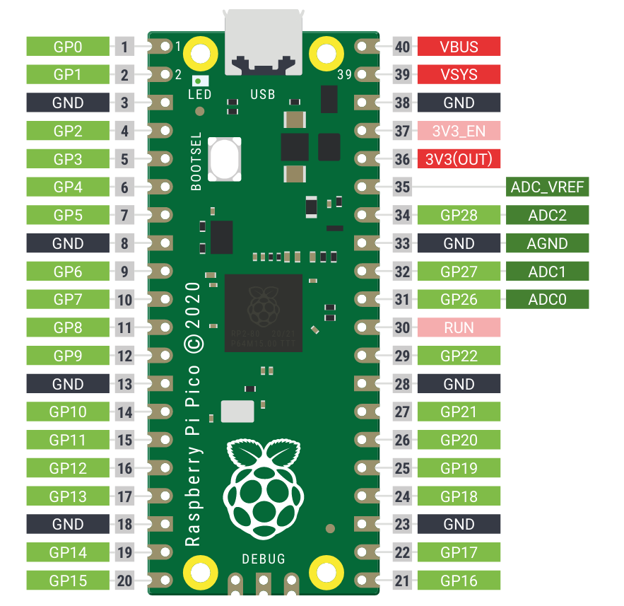
- Attach the male end of these 2 cables, one to GP12 and the other to GP13 on the breadboard (click the Raspberry Pico Pinout Diagram on the left).
- Attach the female end of 2 male-to-female jumper cables, one to IN3 and the other to IN4.
- Attach the male end of these 2 cables, one to GP14 and the other to GP15 on the breadboard.
- Attach a male-to-male jumper cable from a GND on Pico to common blue rail on the breadboard.
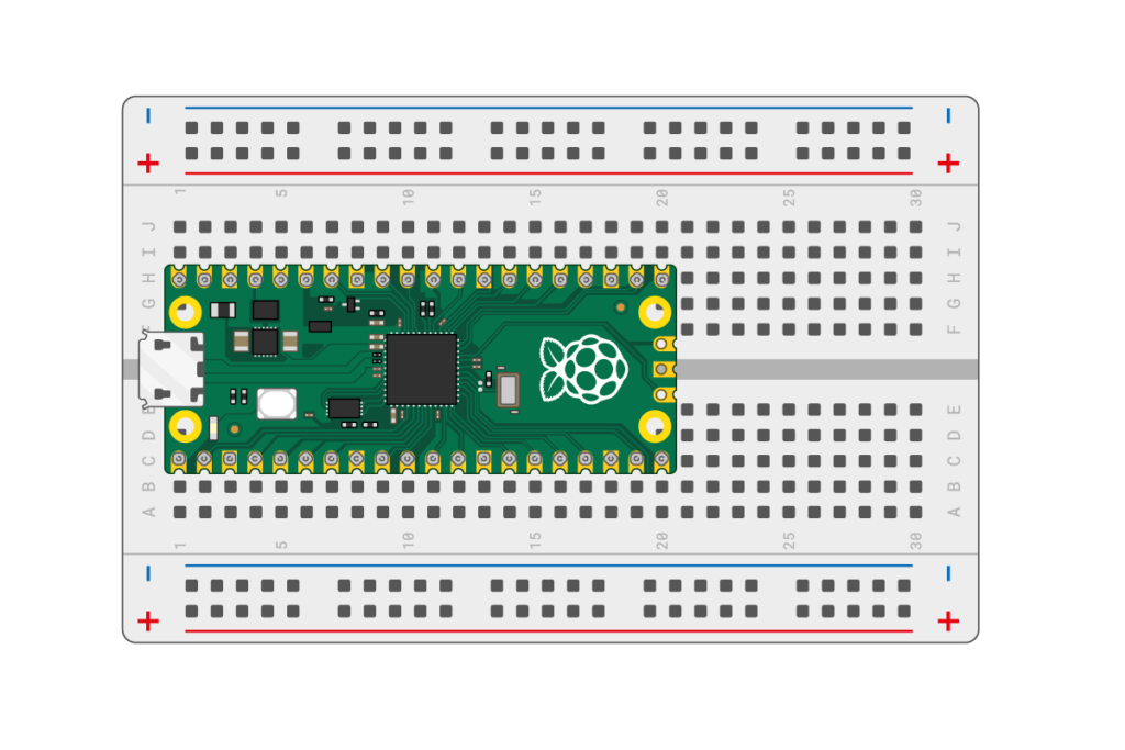
- Attach another male-to-male jumper cable from 3V3 (OUT) to the common red rail on the breadboard (click the Raspberry Pico/breadboard diagram on the left).
Step 2 – We need power!
- Loosen the screws on the 3 remaining terminals on the controller board.
- Attach one end of a male-to-male jumper cable to the 5V terminal and tighten the screw, making sure the cable is secure.
- Insert the other end of the cable to the common power rail.
- Connect the red wire from the battery pack to the 12V terminal on the controller board and tighten securely.
- Connect the black wire from the battery pack AND one end of a male-to-male jumper cable to the GND on the controller board, making sure they are both secured within this one terminal.
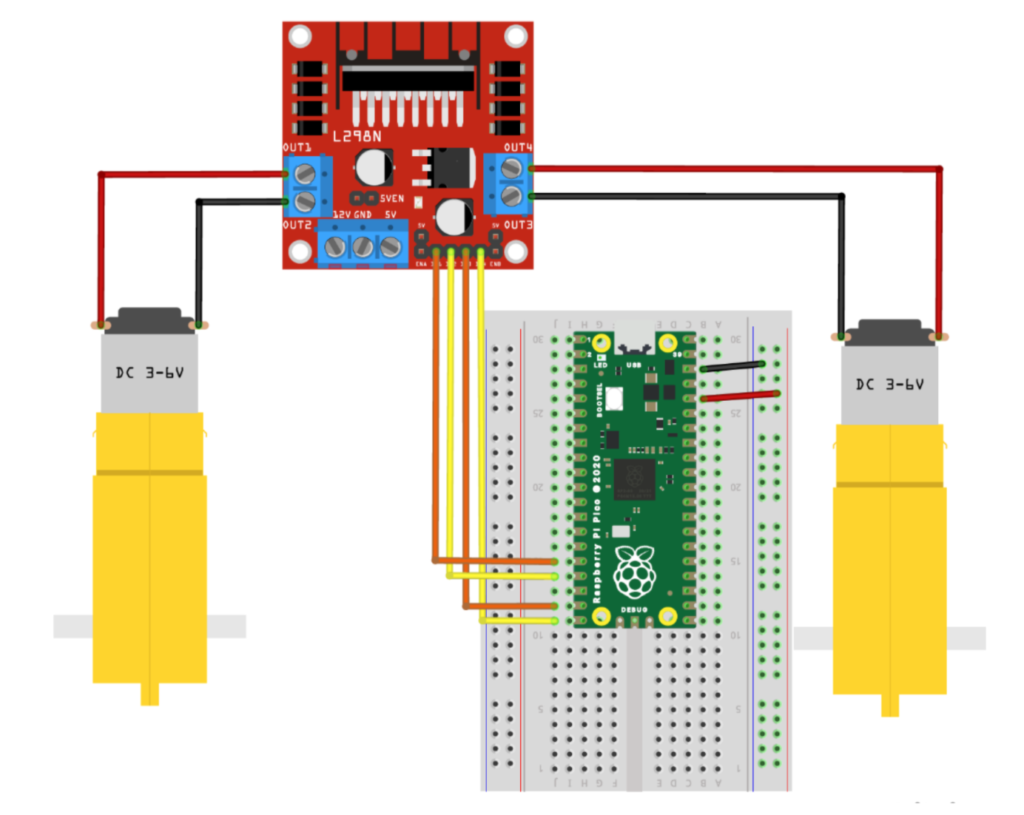
- Insert the other end of the male-to-male cable to a GND on the breadboard. (Refer to the diagram to the left.)
- Insert 4 – AA batteries into the battery pack.
Step 3 – Time to test and configure the motors for your rover
You’ll need to fire up Thonny to begin coding. If you’re thinking – What are you talking about? – then head over here to learn about Pico and how to install Thonny for your project.
- Connect Pico to your computer and open up Thonny
- You’ve connected the motor controller to pins GP12 and GP13, and GP14 and GP15.
- one pin turns the motor in one direction while the other turns the same motor in the opposite direction
- your job is to figure out which is the right motor and which is the left motor – which way do they turn to go forward and backward
- Open Thonny and begin a new file and start with this code:
from machine import Pin
import utime
Remember: the machine library is needed to create a Pin object and the utime library is needed to create a pause (sleep) in your program
4. Create 2 variables for the connections of one the motors. Since one of the motors is connected to GP12 and GP13, you need to set these pins as the output pins like this:
motor_right_fwd=Pin(12, Pin.OUT)
motor_right_bwd=Pin(13, Pin.OUT)
5. Send a high signal (on) and a low signal (off) to the pin.
motor_right_fwd.high()
utime.sleep(3)
motor_right_fwd.low()
6. Save and run the program. The motor should spin forwards for 3 seconds and then stop (if it’s not spinning forward, you can change the pin numbers later. For now, just make sure the motor is spinning in either direction.
7. Now test opposite direction for the same motor by using the following code:
motor_right_bwd.high()
utime.sleep(3)
motor_right_bwd.low()
8. If the motor is not spinning backwards, just swap the pin numbers in your code.
9. Repeat the above steps for the other motor.
10. Mark each motor accordingly (left and right).
Finished code
from machine import Pin
import utime

motor_right_fwd=Pin(12, Pin.OUT)
motor_right_bwd=Pin(13, Pin.OUT)
motor_left_fwd=Pin(14, Pin.OUT)
motor_left_bwd=Pin(15, Pin.OUT)

motor_right_fwd.high()
motor_left_fwd.high()
utime.sleep(3)
motor_right_fwd.low()
motor_left_fwd.low()

utime.sleep(1)

motor_right_bwd.high()
motor_left_bwd.high()
utime.sleep(3)
motor_right_bwd.low()
motor_left_bwd.low()
Construct the chassis and testing your rover
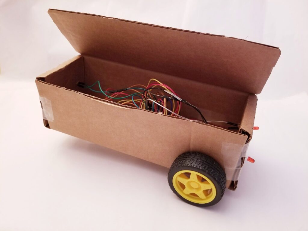
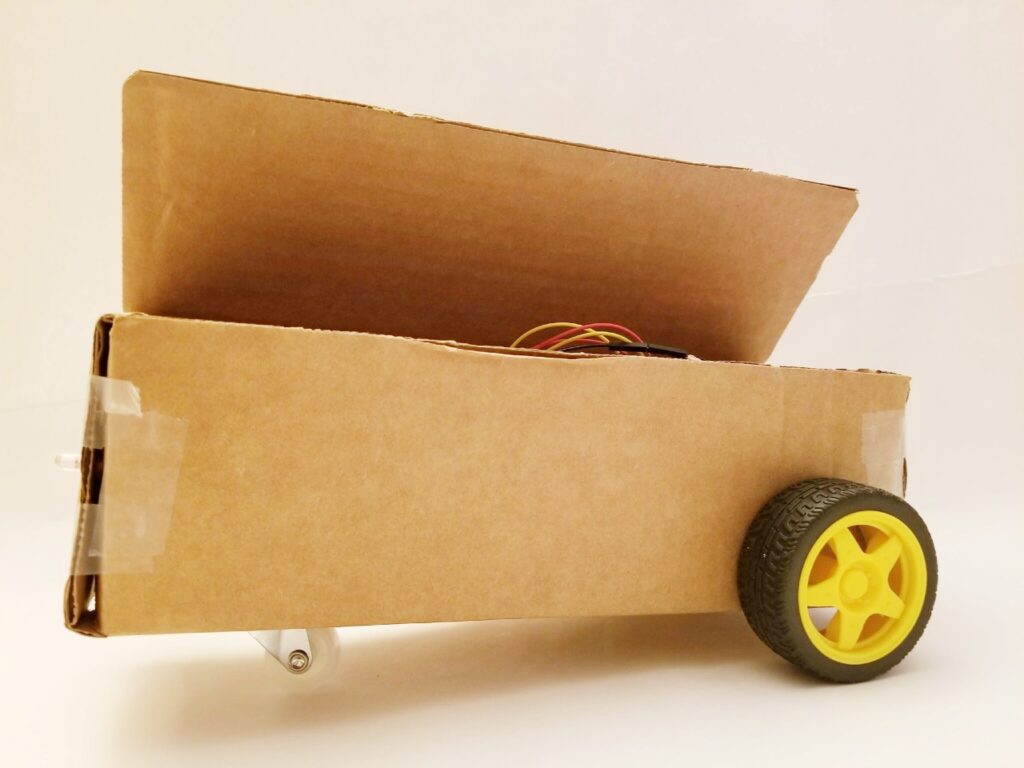
- Find a small cardboard box to serve as your rover.
- Considerations:
- Size of the box (Is it sturdy enough to withstand the weight of the rover’s components? Is it large enough to hold all of the rover’s components?)
- Attaching components (What is needed to keep the items intact?, i.e., scotch or masking tape)
- Place the breadboard, microcontroller (Raspberry Pico), and the motors inside the chassis. Mark where each wheel axle should be located and create the holes for each. Insert each wheel axle into the chassis and secure both motors to the chassis with tape, making sure to place them in their proper place (left and right motor).
- Attach the wheels to each axle.
- Attach the miniature castor wheel underneath the front end of the chassis, making sure it’s centered.
- With your Raspberry Pico attached to your computer, run your code from above to test your rover.
Off the grid: How do you run your code sans computer?
- Save your code directly on your Raspberry Pico as main.py.
- Disconnect the rover from your computer.
- Remove and then replace one of the batteries in your rover and your creation should automatically run the main.py file.