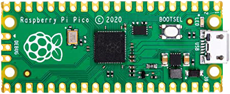
Build and Code a Rover with Raspberry Pi Pico

What is Raspberry Pi Pico?

Developed by Raspberry Pi, Pico is a microcontroller board built on RP2040, a 32-bit dual ARM Cortex-M0+ microcontroller chip.

What is a microcontroller?

A self-contained computer, a microcontroller is a single, integrated circuit that can be programmed to perform a certain task. It’s a small processing unit with a bit of memory that can control other hardware. Look around! You probably have microcontrollers around your house that you use every day (television remote control, burglar alarm, thermostat, etc.). What’s the difference between these items and Raspberry Pico? It’s difficult to make any changes to the software that’s running on your everyday household items. However, Raspberry Pico can be easily reprogrammed with a simple USB connection. Designed for physical computing, Pico uses MicroPython to control LEDs, buttons, sensors, motors, as well as other microcontrollers.

What can you learn when creating with Pico?
  • become familiar with physical computing
  • work with motors, LEDs and sensors
  • connect servo motors
  • and so much more (future lessons)
We are going to learn how to build a rover from scratch, but you will need the following components:
  • Raspberry Pi Pico with *pre-soldered Header Pins (*this is important!)
  • USB to Micro USB Cable, 1.5 ft
  • 2x DC Gear Motors with Plastic Tire Wheels
  • Miniature Castor Wheel
  • Motor Driver Board (L298N)
  • Battery Holder for 4 – AA Batteries
  • Half-size 400-Pin Breadboard
  • 2 – White LEDs
  • 2 – Red LEDs
  • 4 – 100 Ohm Resistors
  • 20 – Female-Male Jumper Wires
  • 20 – Male-Male Jumper Wires
  • Miniature Push Button
  • Small Phillips Screwdriver
  • Cardboard box for rover chassis
  • Scissors
  • Masking tape
  • 4 – AA Batteries
Raspberry Pi Pico
Raspberry Pi Pico
Raspberry Pi Pico Pinout Diagram

Let’s start coding!

Not so fast! Your RP Pico doesn’t ship with the necessary programming software called *MicroPython,
so let’s get that done first.
*MicroPython is a subset of Python and is optimized to run on microcontrollers.
  1. Plug the micro USB cable into Pico’s micro USB port
  2. Hold down the boot selection button (BOOTSEL), shown in the diagram above
  3. While holding the BOOTSEL button down, connect the other end of the micro USB cable to a computer with internet access
  4. Wait 3 seconds and let go of the BOOTSEL button
  5. You should see your Pico appear as a removable drive
  6. Click on the Pico drive and double click on the file named index.htm
  7. When a welcome page appears, click on the MicroPython tab and choose the “Download UF2 file” button and download it to your computer
  8. Once the file has downloaded, close the browser
  9. Open your Downloads folder on your computer, find the UF2 file that you just downloaded and drag it into the Pico’s drive
  10. Congratulations! MicroPython is now installed on your Pico
You’re almost there…just one more thing.
Thonny Integrated Development Environment

Some type of interface is needed to interact with the MicroPython. It’s what’s known as an integrated development environment (IDE). A popular IDE for MicroPython is Thonny, which can be found at thonny.org. Just make sure you download the correct version (Windows, Mac, or Linux).


Thonny Integrated Development Environment

With your Pico connected to your computer and when Thonny is launched, look at the bottom right-hand side of the Thonny window (called the Python Shell) and you should see the word “Python” followed by a version number. Click there and change it to MicroPython (Raspberry Pi Pico). If you don’t see it in the list, click “Configure interpreter” and under the “Interpreter” tab, choose “MicroPython (Raspberry Pi Pico).”


You are ready to write your first program!

How to code using Thonny

In Thonny’s Python Shell window, type the following:

print("Hello World!")

Remember: punctuation matters! It must look exactly like this or you will get an error message.

Now hit the return key. You will see the words Hello World! appear in your Shell.

There’s only one problem…you just directly interacted with Thonny, but your script wasn’t saved anywhere. Let’s deal with that next…
How to save your code

Save the file by clicking on the Save icon.


Choose to save your file directly on “Raspberry Pi Pico”


Save the file as hello.py


To make the program run, you will need to click the white arrow surrounded by a green circle, located in Thonny’s toolbar.
You will now see the words Hello World! appear in the Shell.

Electrical Components:
Pins, Breadboards,
Resistors, and LEDs

GPIO pins – What are they?

General Purpose Input/Output (GPIO) pins allow us to talk to hardware. There are 40 pins on a Pico, where some have a fixed purpose. (More on that later.) Do yourself a favor and keep this pinout diagram handy. It will really make connecting components much easier for any project.

How to make Pico’s LED light up

Located next to the microUSB connector, the SMD LED will light up when it’s programmed to do so. It’s connected to GP25. Let’s try it out!

  • Connect Pico to your computer and launch Thonny
  • Place your cursor in the script area and start programming by typing the following:
from machine import Pin
import utime
led = machine.Pin(25, machine.Pin.OUT)
while True:
    led.value(1)
    utime.sleep(1)
    led.value(0)
    utime.sleep(1)
  • Save the file on Pico as blink.py and run your program
  • It should turn on and off
  • To stop the program, click on the STOP sign in Thonny’s toolbar
Breadboard – It’s not what you think!

Breadboards are used to easily connect your microcontroller to various components – no soldering required. Simply insert your Pico, jumper wires, LEDs, resistors, sensors to connect your creations. It’s a great way to practice your physical computing skills because it can be used over and over again for a multitude of projects.

In the left image, the green lines show how the holes are connected to metal strips within the breadboard. The holes along both the top and bottom edges (called power rails) each have positive + and negative – symbols.

Resistors – Go with the Flow

Resistors:

  • control the flow of electrical current
  • are available in different values
  • values are measured in units known as ohms (Ω)
  • the higher the number of ohms, the more resistance provided
  • 330 Ω is suggested for Pico
  • numbered values or colored stripes may be printed on them to denote their value
  • can be inserted either way (notice the colored stripes)

When working with physical computing projects, resistors are used to prevent LEDs from drawing too much current. This avoids damage to your LEDs and Pico.

LEDs – Let them shine!

LEDs (Light-emitting diodes):

  • an output device
  • can be controlled directly from your program
  • available in a variety of colors, shapes, and sizes
  • do not use LEDs designed for 5V or 12V power supplies
Attaching your Pico to a breadboard

Your Pico should have pre-soldered header pins. (If not, the header pins will have to be individually soldered to the Pico. This is for the more advanced, which won’t be shown here. Future lessons about soldering techniques will be available.)

  • Insert into the breadboard as shown here. It may be a little difficult to attach. Make sure the Pico is straddling the centerline of the breadboard and all pins are lined up. The microUSB port should be positioned close to the edge of the breadboard.
  • Carefully push the Pico all the way down into the breadboard. Just be careful not to bend any pins.
Let’s work with external LEDs

Each leg of an LED has job to do:

  • anode (long leg)
    • positive circuit connection
    • must be connected to GPIO pin with a resistor
  • cathode (short leg)
    • negative circuit connection
    • must be connected to a ground pin

Male-to-male (M2M) jumper wires:

  • used to connect Pico with your LED and ground pin

How to set up a complete circuit

  1. Insert either end of a 330 Ω resistor into the breadboard in the same row as Pico’s GP15 pin (lower left-hand side) and insert the other end 4 spaces the right.
  2. Insert the anode (longer leg) in the same row as the resistor, but below the center gap of the breadboard.
  3. Insert the cathode (shorter leg) in the same row as the resistor and anode, above the center gap of the breadboard.
  4. Insert a M2M jumper wire in the same row as the cathode and insert the other end into the negative side of the breadboard’s power rail.
  5. Finally, insert another M2M jumper wire from any available negative port and insert the other end into one of Pico’s ground pins.
  6. Your circuit is now complete.
  7. We are how ready to code – connect Pico to your computer and fire up Thonny!
  8. Open your saved blink.py file and simply change the pin number from 25 to 15, as shown below.
  9. Save and run your file and let the magic begin!
from machine import Pin
import utime
led = machine.Pin(15, machine.Pin.OUT)
while True:
    led.value(1)
    utime.sleep(1)
    led.value(0)
    utime.sleep(1)