Raspberry Pi Pico Rover
Let’s Start Coding with Raspberry Pi Pico
Set up MicroPython, learn how to use Thonny, and build simple LED circuits before moving on to the full rover build.
Before building the full rover, start here. This page walks through the coding setup and core electronics skills from the project: installing MicroPython, configuring Thonny, saving your first Python file, learning how GPIO works, and lighting both the built-in and an external LED.
On This Page
- Install MicroPython on your Pico
- Set up the Thonny IDE
- Write and save your first Python program
- Learn GPIO pins, breadboards, resistors, and LEDs
- Blink Pico’s built-in LED
- Build and code an external LED circuit
You’ll Need
- Raspberry Pi Pico with pre-soldered header pins
- Micro USB cable
- Computer with internet access
- Thonny IDE installed
- Breadboard
- 330 Ω resistor
- LED
- Male-to-male jumper wires
1. Install MicroPython on Your Pico
Your Raspberry Pi Pico does not ship with MicroPython already installed, so this is the first step before writing code.
- Plug the micro USB cable into Pico’s micro USB port.
- Hold down the BOOTSEL button on the Pico.
- While holding the button, connect the other end of the cable to a computer with internet access.
- Wait about 3 seconds, then release the BOOTSEL button.
- Your Pico should appear as a removable drive.
- Open that Pico drive and double-click the file named index.htm.
- When the welcome page opens, click the MicroPython tab and choose Download UF2 file.
- After the download finishes, close the browser.
- Open your computer’s Downloads folder and drag the UF2 file onto the Pico drive.
- MicroPython is now installed on your Pico.
MicroPython is a subset of Python designed to run on microcontrollers.
2. Set Up Thonny
To interact with MicroPython on the Pico, you’ll need to use an integrated development environment (IDE). A popular IDE for MicroPython is Thonny, which can be found at thonny.org. Just make sure you download the correct version (Windows, Mac, or Linux).
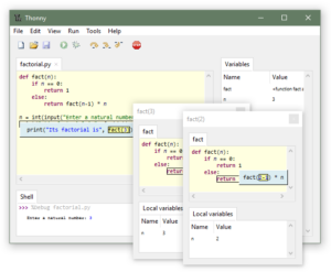
- Install Thonny on your computer.
- Connect your Pico and open Thonny.
- Look at the bottom-right area of the Thonny window.
- If needed, change the interpreter to MicroPython (Raspberry Pi Pico).
- If it is not listed, choose Configure interpreter and select MicroPython (Raspberry Pi Pico) under the Interpreter tab.
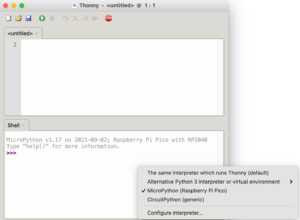
Once that is set, you are ready to begin writing code directly for the Pico.
3. Write Your First Program in Thonny
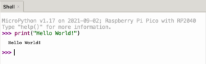
Start by typing this in Thonny’s Python Shell:
print("Hello World!")Press Return, and you should see Hello World! appear in the Shell.
Reminder: punctuation matters. Type it exactly as shown.
4. Save and Run Your Code
Typing in the Shell works, but it does not save your program. Now create and save a real Python file.
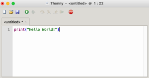
- Type the same line of code in the script area above the Shell.
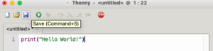
- Click the Save icon.
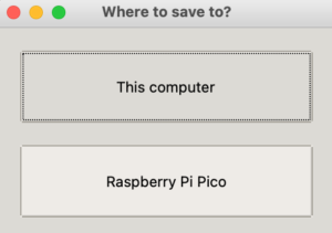
- Choose to save the file directly on Raspberry Pi Pico.
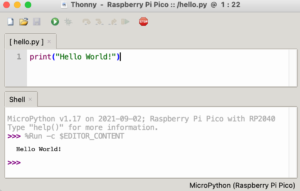
- Name the file hello.py.
- Click the white arrow in the green circle to run the program.
- You should see Hello World! appear in the Shell.

Important: Saving your file onto the Pico lets you build a library of programs directly on the device.
5. Learn the Core Electronics
Before building the rover, it helps to understand the components you will use in your circuit work.
GPIO Pins
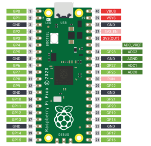
GPIO stands for General Purpose Input/Output. These pins let your Pico communicate with hardware. The tutorial notes that the Pico has 40 pins, and some have fixed purposes. Keep a pinout diagram nearby whenever you build.
Breadboard
A breadboard lets you connect your Pico to components without soldering. It is reusable, quick to modify, and ideal for learning physical computing.
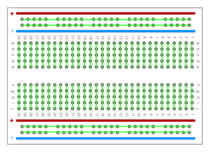
The top and bottom rails are power rails, and the rows in the middle are electrically connected in grouped strips.
Resistors
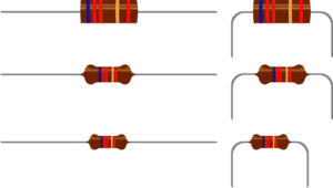
- Control the flow of electrical current
- Come in different values measured in ohms (Ω)
- Help prevent LEDs from drawing too much current
- 330 Ω is suggested for Pico
LEDs
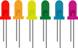
- An output device you can control with code
- Available in many colors, shapes, and sizes
- Should match the power requirements of your project
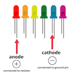
For external LEDs, the anode is the longer leg and connects to the GPIO side of the circuit through a resistor. The cathode is the shorter leg and connects to ground.
6. Blink Pico’s Built-In LED
The Pico’s onboard LED is connected to GP25. You can use it to test that your setup is working.
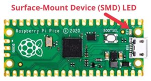
Open a new script in Thonny and type this code:
from machine import Pin
import utime
led = machine.Pin(25, machine.Pin.OUT)

while True:
    led.value(1)
    utime.sleep(1)
    led.value(0)
utime.sleep(1)- Save the file on the Pico as blink.py
- Run the program
- The onboard LED should turn on and off repeatedly
- To stop the program, click the STOP button in Thonny
7. Attach Pico to the Breadboard
Your Pico should have pre-soldered header pins before placing it into the breadboard.
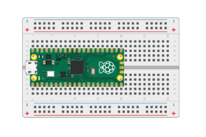
- Place the Pico so it straddles the center gap of the breadboard.
- Line up all the header pins carefully.
- Position the microUSB port close to the edge of the breadboard.
- Press down carefully so the board is fully seated without bending pins.
8. Build and Code an External LED Circuit
Now move from the onboard LED to an external circuit connected through the breadboard.
Build the Circuit
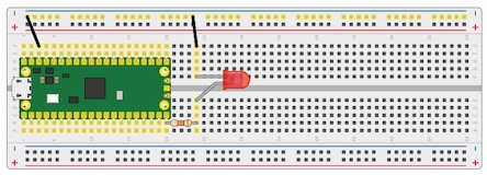
- Insert either end of a 330 Ω resistor into the same row as GP15 on the Pico.
- Insert the other end of the resistor four spaces to the right.
- Insert the LED’s anode (long leg) in the same row as the resistor, below the breadboard’s center gap.
- Insert the LED’s cathode (short leg) in the same row, above the center gap.
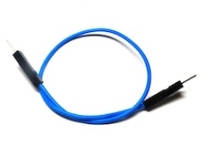
- Insert a male-to-male jumper wire in the same row as the cathode and connect the other end to the negative power rail.
- Insert another jumper wire from an available negative port on the breadboard to one of the Pico’s ground pins.
- Your circuit is now complete.
Update the Code
Open your saved blink.py file and change the pin number from 25 to 15:
from machine import Pin
import utime
led = machine.Pin(15, machine.Pin.OUT)

while True:
    led.value(1)
    utime.sleep(1)
    led.value(0)
    utime.sleep(1)
Save the file and run it. Your external LED should begin blinking.